Electron Beam Welding of Busbars for Electric Vehicles
Introduction
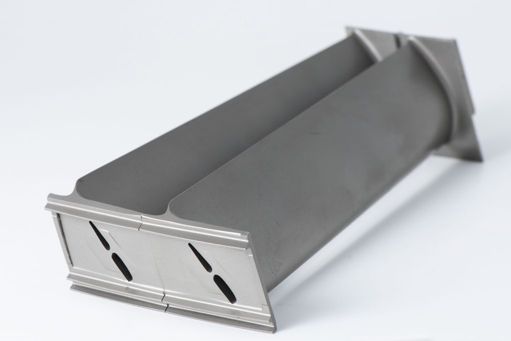
Busbars are an essential component of an electric vehicle.
Typically made of conductive alloys such as aluminium, bronze, or copper, they distribute power between individual cells, as well as the battery packs to the motors.
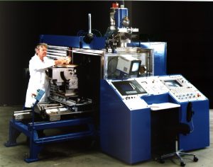
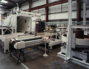
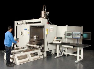
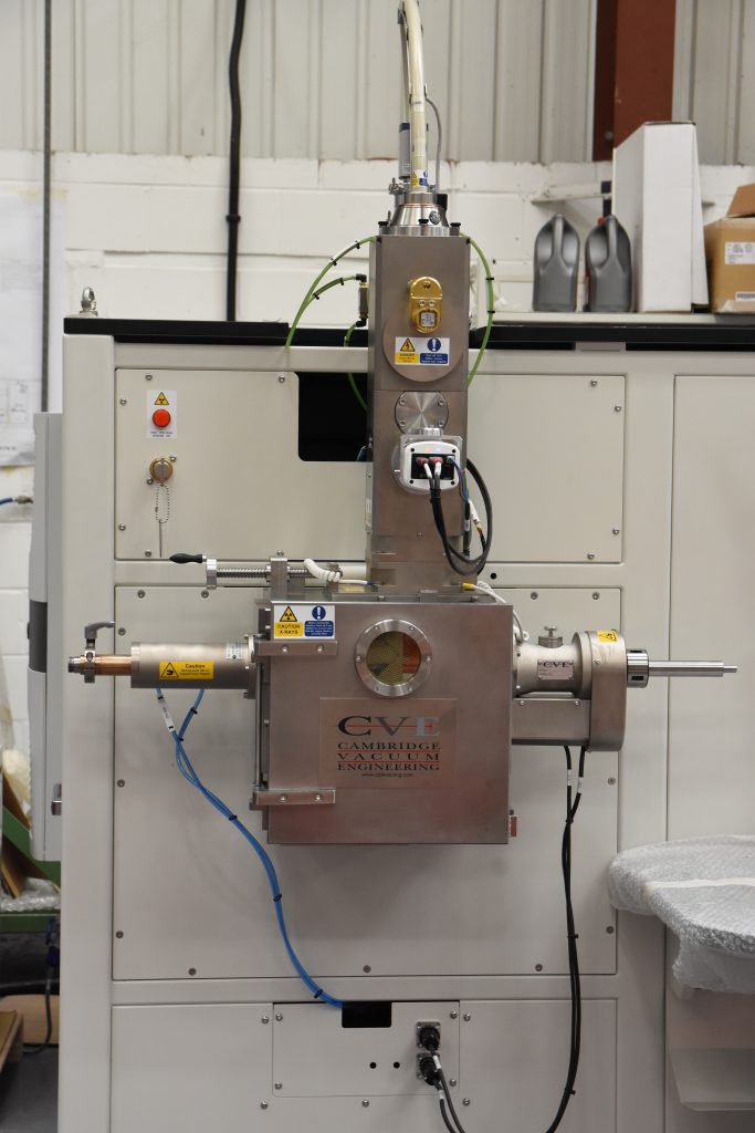
CVE, designers and manufacturers of electron beam and laser welding process solution systems, have collaborated with TWI, membership-based research and technology organisation, to explore the feasibility of using the electron beam welding process for interconnection of cells and for joining busbars to the powertrain.
Background
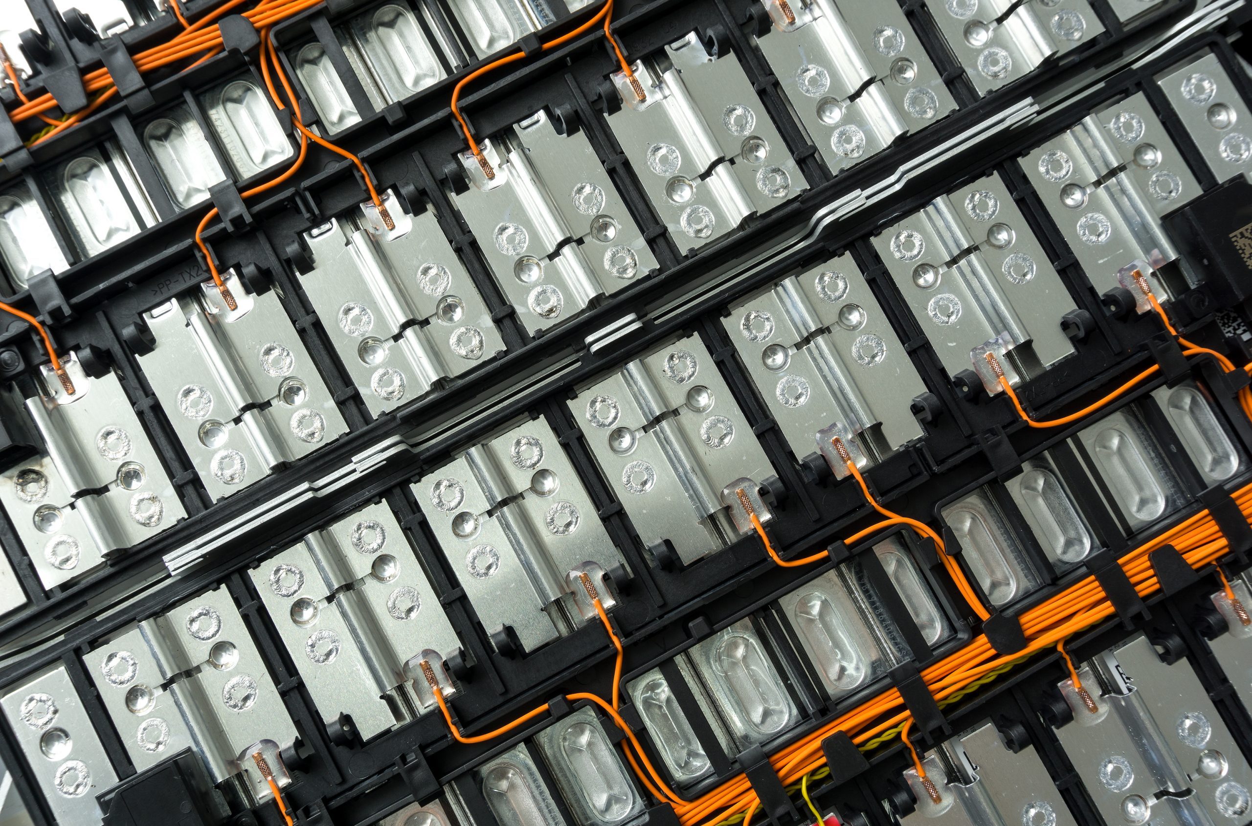
The structure of a typical electric vehicle battery pack starts as a cell. Designs vary across manufacturers, but the industry has settled on 21700 cells as standard.
Battery packs welded together with busbars, typically 60-100 cells, create a module, and multiple modules (6-40) make a pack.
The welded busbars are typically produced from copper with nickel plating.
This new design represents a challenge for OEMs. The components are rapidly developing and replacing traditional components that have been manufactured for hundreds of years.
The International Energy Agency predicts that there will be 230m electric vehicles worldwide by 2030, signalling an industry requirement for a high-quality, reliable, and quick welding process for battery pack production.
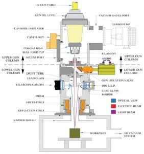
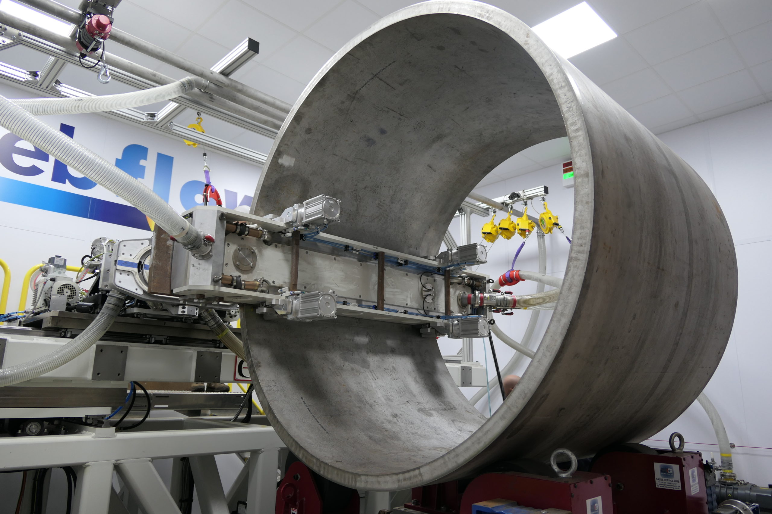
Wide Angle Deflection Electron Beam Welding
CVE and TWI ran a series of test welds using a method of wide-angle deflection electron beam welding.
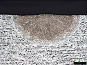
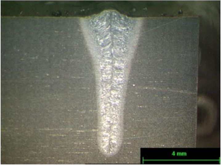
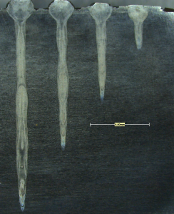
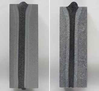
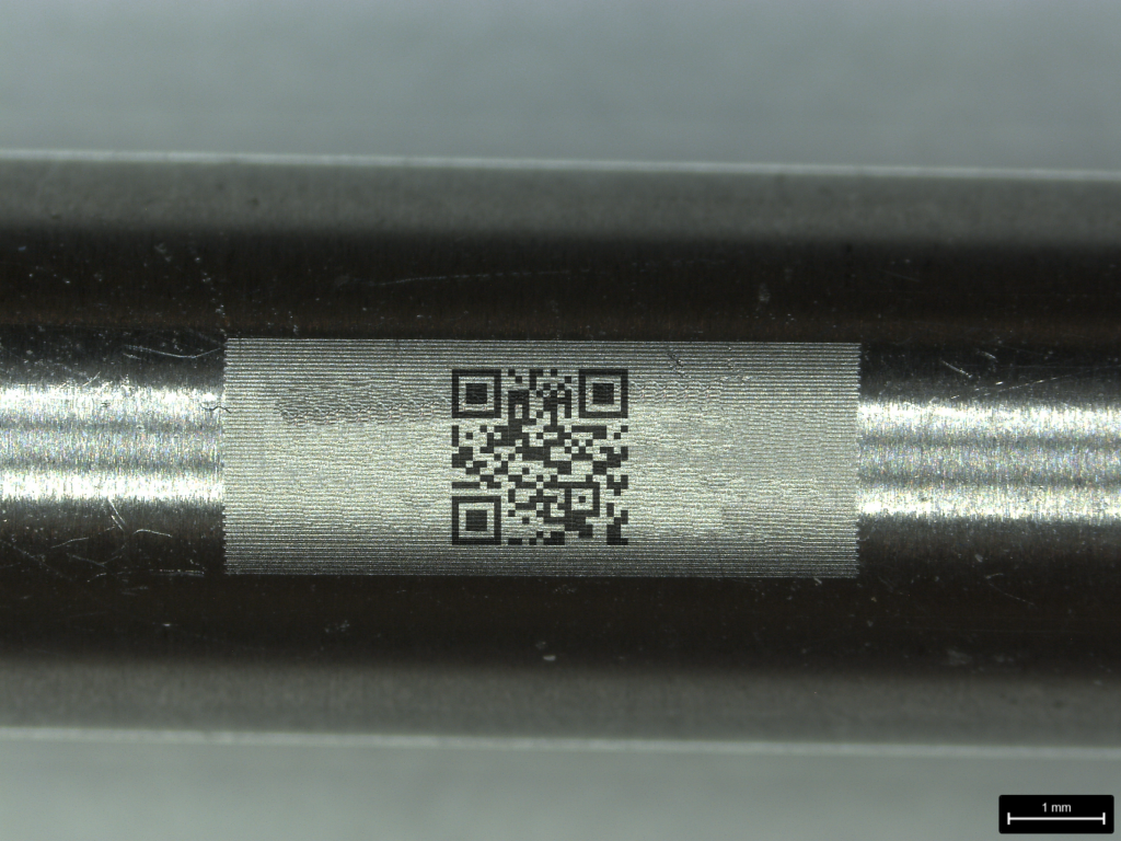
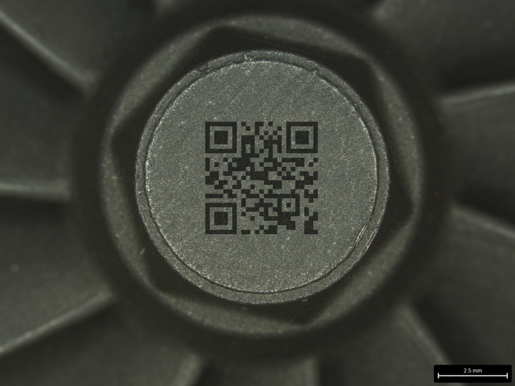
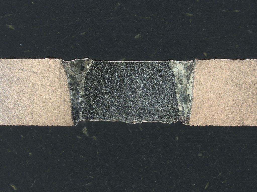
Electron beam spot melting trials on a 450-micron steel sheet (bus bar battery tab) showed that the test welds achieved a consistent depth of up to 200 microns.
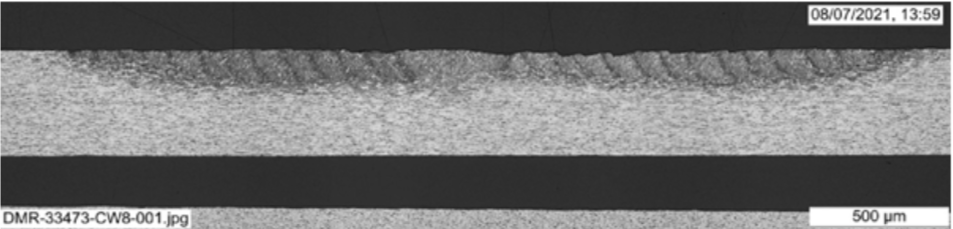
Figure 1. 60kV, 2mA, 2msec spots.
Solution
CVE and TWI successfully developed high-quality welds joining bus bars to battery cell samples.
The investigation also found electron beam welding to be a much quicker process in comparison to resistance and laser welding.
The typical time to manufacture one battery pack using resistance welding is 12,000 seconds and 1,260 seconds using laser welding. In comparison, electron beam welding has demonstrated a speed of just 189 seconds per battery pack, with anticipated developments expected to take this number closer to just 75 seconds per pack, representing a 99.38% time saving.
The weld time comparison across resistance, laser, and electron beam welding results are shown in the table below.
| Time to weld one cell (4 welds) | Time to manufacture one battery pack | |
| Typical for resistance welding | 4 seconds | 12,000 seconds |
| Typical for laser welding | 0.42 seconds | 1,260 seconds |
| Demonstrated speed for electron beam | 0.063 seconds | 189 seconds |
| Anticipated electron beam development | 0.025 seconds | 75 seconds |
Applications and Further Developments
There are many other advantages of electron beam welding for this application, including:
- The weld quality is highly consistent
- Electron beam welding is at least 10x faster than laser
- There is no requirement for gas
- Potential to implement vacuum load-lock systems
- The vacuum chamber contains the welding process. This results in less spatter, so the welds are greatly more consistent than when using laser welding
- An electron beam is less sensitive to reflectivity, the beam being a finely focused stream of electrons, rather than monochromatic coherent light (photons) like a laser
- The vacuum environment closes micro-gaps, resulting in a stronger weld
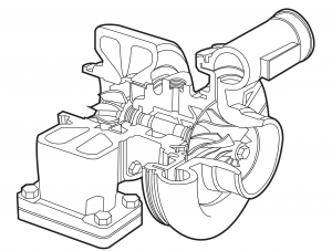
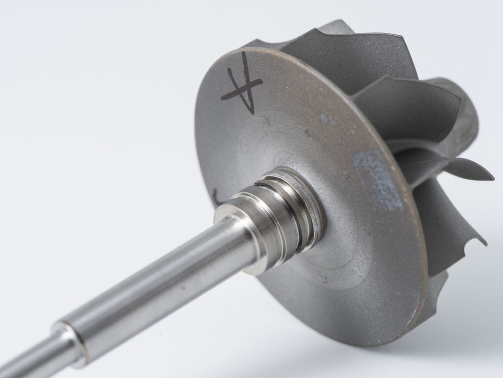
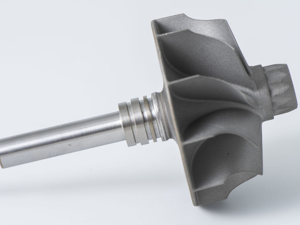
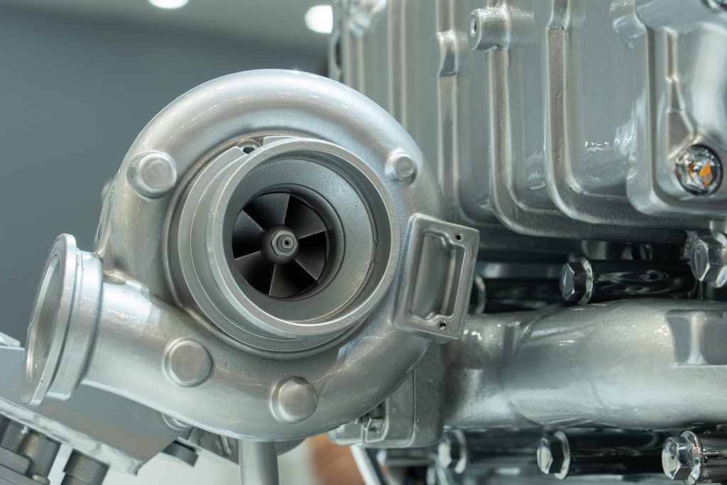
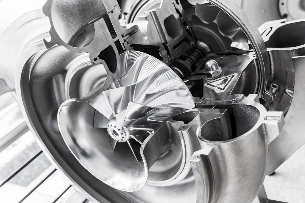
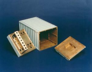
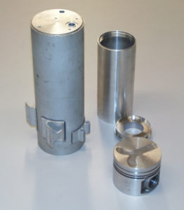
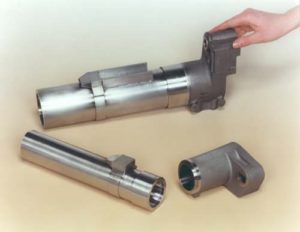
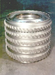
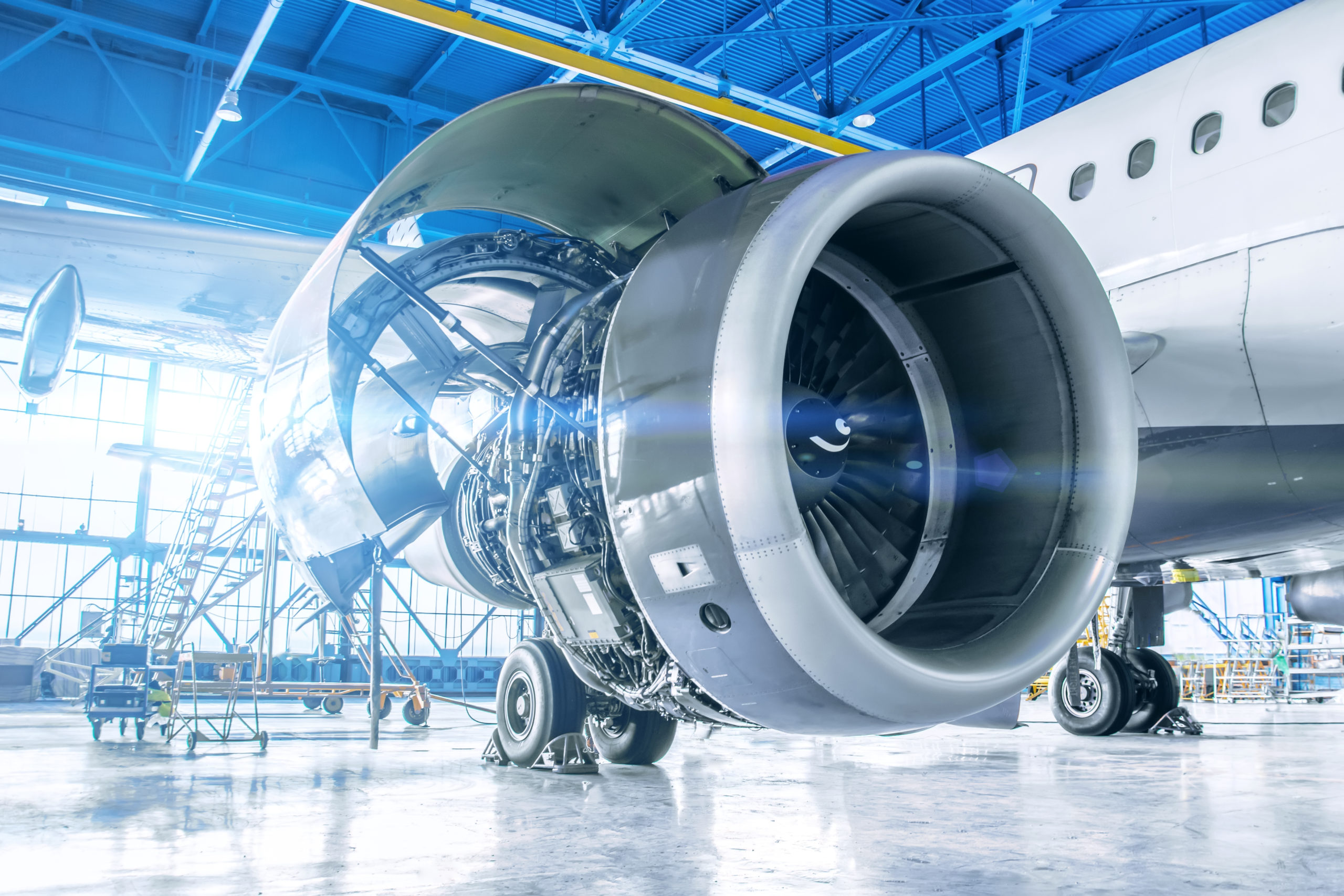
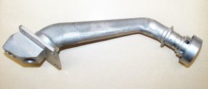
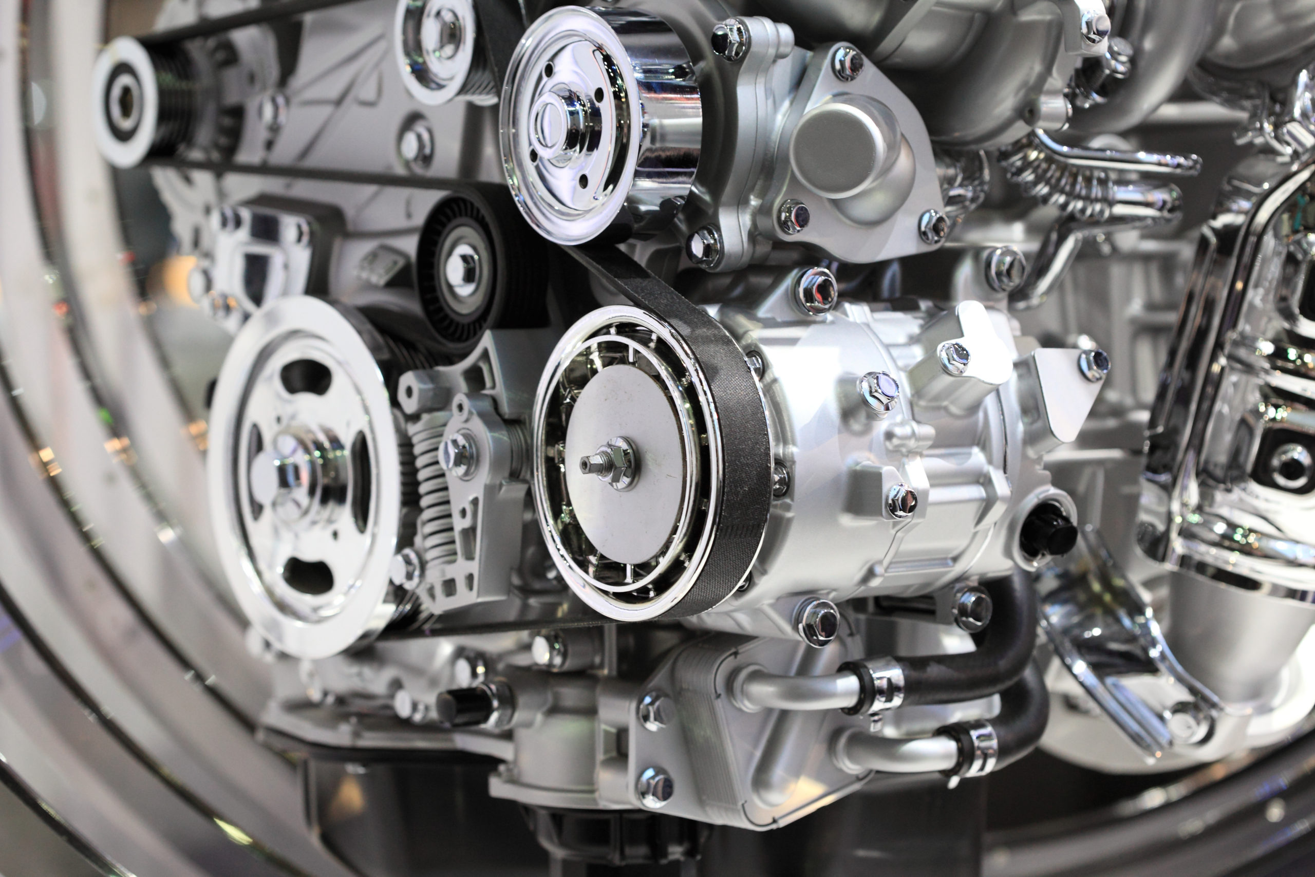
Electron beam welding is already a well-established process for high-volume automotive components, such as turbochargers.
Production possibilities include implementing a vacuum load lock system, which would allow for high-speed cycles between assemblies, therefore resulting in very fast cycle times being readily achievable.