Life at CVE: Social and Wellbeing Programme

Thrive & Be! with CVE

CVE run an extensive Social and Wellbeing Programme for colleagues throughout the year, offering something for everyone: from social activities to health MOTs and mental health seminars.

The programme, called Thrive and Be! with CVE covers all of the activities that take place and you can find out more about them by scrolling through this page.


BBQs and Food Trucks


Go-Karting

Theatre Trips 


Horse Racing


Cambridge Dragon Boat Race


Mental Health Awareness and First Aid

Wellbeing Seminars


Subsidised Gym Membership


Badminton

Five-A-Side Football

Golf

Pilates


Table Tennis

Health MOTs

Flu Vaccines

Free Fruit

Financial Wellbeing

Financial wellbeing seminars focused on creating financial plans and budgets, withstanding financial shock, and essential money management skills and good habits.


Training

CVE are proud to provide training and development opportunities for employees to support them throughout their professional career.

Removing the Bottleneck in Welding Electrical Conductors for EVs

Introduction

The need to increase the rate of joining electric-conducting components is of critical importance to the electric vehicle sector, as it is emerging as the bottleneck of manufacturing.

The components of significance are electrical connectors and wires that can be sub-millimetre thick foils or several millimetre thick rectangular section wires. Typically, copper is used for these components due to its low cost, high electrical conductivity, and plentiful availability. Most high-throughput manufacturers choose laser welding as their joining process due to the high thermal conductivity of copper and the low thermal input that is required for the components.

Laser Welding of Copper

Laser welding of copper is challenging, primarily due to the wavelengths of commercially available lasers typically being red and infrared. These do not couple into copper easily due to the high reflectivity. The reflectivity also contributes to limiting the beam angle of incidence, meaning the process must integrate mechanical repositioning of the welding head.

The short focal depth of field of a welding laser also creates a high failure rate in the manufacturing. It requires high-precision machines in the manufacturing line to ensure the parts are prepared and held accurately at the correct working distance so that the weld executes correctly and repeatably.

These drawbacks experienced when laser welding copper are issues that are not relevant to electron beam welding.

The Advantages of Electron Beam Welding

Electron beam welding suffers no reflectivity issues that prevent it from coupling into materials. Furthermore, the focal depth is multiple times longer and is rapidly adjustable during the process as the focusing is performed by electromagnetic coils.

The rapid speed of beam positioning by electromagnetic coils and commercial availability of significantly higher beam power supplies are the most important advantages in allowing electron beam to process hundreds of thousands of copper welds per minute.

The rapid rate of processing means the seconds taken for the vacuum chamber to evacuate ready for welding become negligible. Furthermore, the fact that the welds are performed in a vacuum chamber mean the resulting weld has no porosity and impurities in the connection, optimizing electrical performance and vehicle efficiency.

Conclusion

CVE build both laser beam and electron beam welding machines, as well as tailor them with numerous customisations for specific manufacturing requirements. In June, we launched a new electron beam welding machine for electric vehicle components including batteries, shunt resistors, motor stators, hairpins, and inverters.

KTP: Laser Welding in Vacuum

What is a KTP?

A KTP is a joint project between a UK university and a UK business, running for between 1 to 3 years. It aims to join the UK’s world-leading research sector (18 of the world’s top 100 universities are British and UK universities occupy spots 2 and 4) with UK businesses.

This embeds the Union’s world-beating academic knowledge into its commercial sector and equally ensures that the research sector is aware of the needs of modern business. This gives rise to a tripartite arrangement between the university, company, and the ‘KTP Associate’ responsible for managing the partnership and executing the project.

Grants are awarded by the funding body, Innovate UK, and there are currently 800 KTPs running throughout the country. The projects have been very successful, bringing an average of £8 of return for every £1 investment.

Project Overview

This KTP is a partnership between CVE and Cranfield University’s Welding and Additive Manufacturing (WAM) Centre towards developing laser in vacuum welding. The project started in January 2021 with wide-ranging goals covering both process and machine.

The process side involves understanding the response of materials to different parameters in LiV welding while the machine side involves solving the engineering problems preventing LiV welding’s industrial viability.

After all, a single good weld is of little inherent value, a machine must be able to produce excellent welds consistently, for many years.

Cranfield University

This exclusively postgraduate institution traces its roots back to the aftermath of the Second World War, when the Royal College of Aeronautics was established at the RAF airbase of Cranfield, Bedfordshire, in 1946.

In 1969, the College was incorporated by Royal Charter into the Cranfield Institute of Technology, by now having expanded from aeronautics to cover manufacturing and management.

Today, Cranfield covers a broad variety of sectors, from aerospace and defence to environment and agrifood. The university’s reputation for high-quality and commercially relevant research makes it a trusted industrial partner in many sectors.

Cranfield has been offering its Welding MSc course for 60 years, with many of the UK’s largest companies’ manufacturing departments containing Cranfield alumni, from senior management down to junior engineers. At the recent 60th Anniversary of the Welding MSc, many of these graduates returned to where their long and illustrious careers began to celebrate Cranfield and the WAM Centre’s proud history and to look forward to a bright and innovative future.

Figure 1. Cranfield’s welding and additive manufacturing facilities. Image courtesy of Cranfield University.

Cambridge Vacuum Engineering

CVE also has a long and accomplished history, with more than 60 years of experience in manufacturing electron beam welding machines and vacuum furnaces. Having delivered over 1,000 machines to customers across the globe, we have decades of experience and institutional know-how of building and maintaining vacuum power beam welding systems.

With offices in the US and China, and the main manufacturing site just outside Cambridge, UK, CVE offers rapid, high-quality service support to its international customer base. The machines leaving the factory show both performance and longevity, with some of our customers still happily using 25+ year old machines.

A few years ago, we expanded our offering to include laser in atmosphere welding machines and laser welding in vacuum machines. Conventional laser welding is an established technology and CVE’s expertise with tooling, operator interfaces and safety made the expansion to conventional laser welding machines seamless. With vacuum laser welding, a newer technology, more complex challenges requiring innovative solutions were encountered.

Birds eye view of Cambridge Vacuum Engineering

Figure 2. CVE’s site.

Laser in Vacuum Welding: A History

Laser welding in a vacuum was initially developed in Japan in the 1980s. It was developed to disperse the plasma plume so detrimental to high-power CO2 lasers. Vacuum laser welding did not see particular interest or uptake until the early 2010s.

Over the last years both academic and industrial interest has grown significantly, with the technology being a more reliable and economic alternative to electron beam in some applications, and a higher quality alternative to conventional laser welding in others.

Laser in Vacuum Welding: Benefits

Laser in vacuum allows penetration depth and weld quality previously only achievable with electron beam welding, while offering a flexibility and reliability that EB can struggle to match.

This is due to the physics of vacuum, with the reduction in boiling point seen by all materials at reduced pressure allowing more material to be vaporised by the laser beam and the weld to thereby penetrate deeper.

The quality comes primarily from the ease of outgassing in vacuum as gases within the keyhole suffer no impediment to their escape from surrounding atmospheric gas, instead the vapourised metal can escape the keyhole and melt pool before the material resolidifies and pores are formed.

The plume normally seen above the weld is mostly absent in vacuum (depending on the vacuum level) due to the same ease of dispersal in vacuum, this reduces the friction on the melt pool partially responsible for spatters.

The advantage over electron beam comes from the laser beam itself, being unaffected by magnetic fields and not producing X-rays. The comparison between the two technologies is complex and both have their own advantages and drawbacks. For a full comparison of conventional laser, electron beam, and laser in vacuum you can read our post about it here.

Laser in Vacuum Welding: Challenges

The challenges involved in LiV welding can be sorted into two broad categories: process challenges, and engineering challenges in the design of machines.

Process challenges are application-specific (root porosity and bulging problems in higher penetration applications, for example) and require a reliably working machine to test out and solve. A reliably working machine requires overcoming at least some of the engineering challenges involved in LiV welding, making these the priority of the project.

Now that these challenges are overcome, focus turns to application-specific challenges, and the assessment of LiV’s suitability for sectors.

The KTP So Far

The first task for the team was an understanding of what exactly the challenges facing us were. The problem of window contamination was intuitively understandable but needed detailed study to fully comprehend and then solve. With a working prototype available from CVE’s internal development, this was used as the starting point. After some weeks of testing, the window contamination problem was well understood, and this knowledge was used as the base for its eventual solution.

The window being referred to is the laser coupling-in window, this is a crucial component as it allows the processing laser beam into the vacuum chamber. As the laser beam leaves the laser, it is launched into a fibre, which is in turn connected to a laser head which collimates and focusses the laser. The laser, fibre delivery, and focussing head are all located outside the vacuum chamber, the laser must shine through a highly transparent (to the laser’s wavelength) window and thereby weld in the chamber. Welding, being an energetic process, throws up debris which contaminates the window, absorbing laser energy and making the window eventually unusable.

Window contamination was found to take two forms: metal vapour, and spatters. Metal vapour being the metal evaporated from the weld and leaving the keyhole, this travels and deposits on the first surface it meets. If this surface is the laser coupling-in window, the window slowly loses transmissivity over its entire face leading to a loss of power reaching the weld, and eventually defocussing the beam as the window heats and deforms turning the otherwise flat window into a curved lens (known as thermal lensing). This is very detrimental to the weld and, while some power loss is tolerable and can be compensated for, the combined effect of power loss and thermal lensing lead to unacceptable welds.

The second form of contamination, spatter, is the more random of the two. Metal vapour can be expected to provide a constant and predictable degradation of the window’s performance. Spatters, on the other hand, are ejected at essentially random directions from the weld. The spatters vary in size and speed, with larger and faster spatter being produced at the higher powers and penetration depths. Spatters striking the laser window produce small spots opaque to the laser, these spots then absorb heat from the laser each time it is fired and can expand slowly over time, as surrounding material is heated and made less transmissive leading to a runaway process. If a spatter is large enough, it can make a window unusable in a matter of seconds.

Figure 3. A window irreparably damaged by a single large spatter.

Figure 4. A window significantly degraded by metal vapour.

Developing a Solution

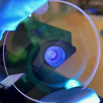
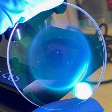
The above knowledge was instrumental in developing a solution as it allowed concepts and ideas to be adapted based on evidence. For example, an early concept solution was a special coating on the window to stop metal vapour adhering to it, like anti-fog coatings on glasses. Without detailed knowledge of the problem, it would be easy to think this is a complete solution. However, with more detailed knowledge we can immediately spot that this does not solve the spatter problem as no coating can both stop a flying spatter and be extremely transparent to IR radiation.

The first window protection system prototype, while effective at protecting the laser window for a time, caused a significant secondary problem: soot generation. This has been covered in some detail in our previous post so head over there to read more on the subject. To combat the soot generation problem, an entirely new solution was required, and armed with the knowledge of the window contamination problem and the soot problem, it was developed and tested. The new solution avoids the soot problem and produces long window lifetimes on the order of hours at medium powers. Simultaneously, a window exchange system was designed for rapid change-over of laser windows. The long window lifetime and short exchange time allow the LiV process to compete with EB’s comparable tungsten filament change process, a key milestone in commercialisation of the technology.

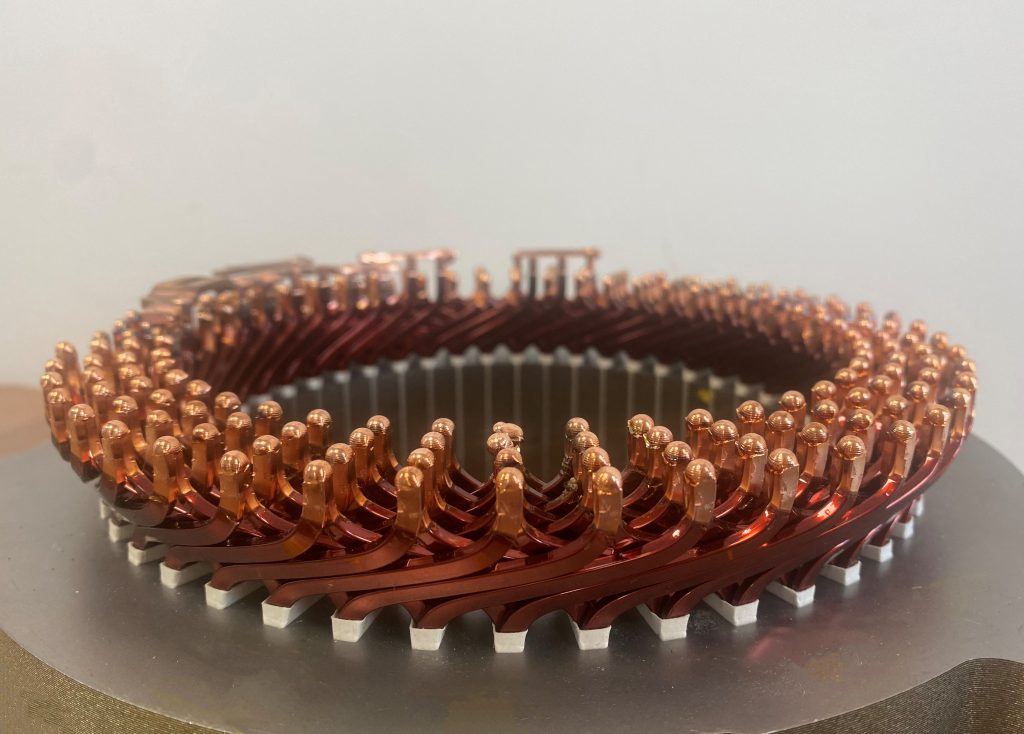
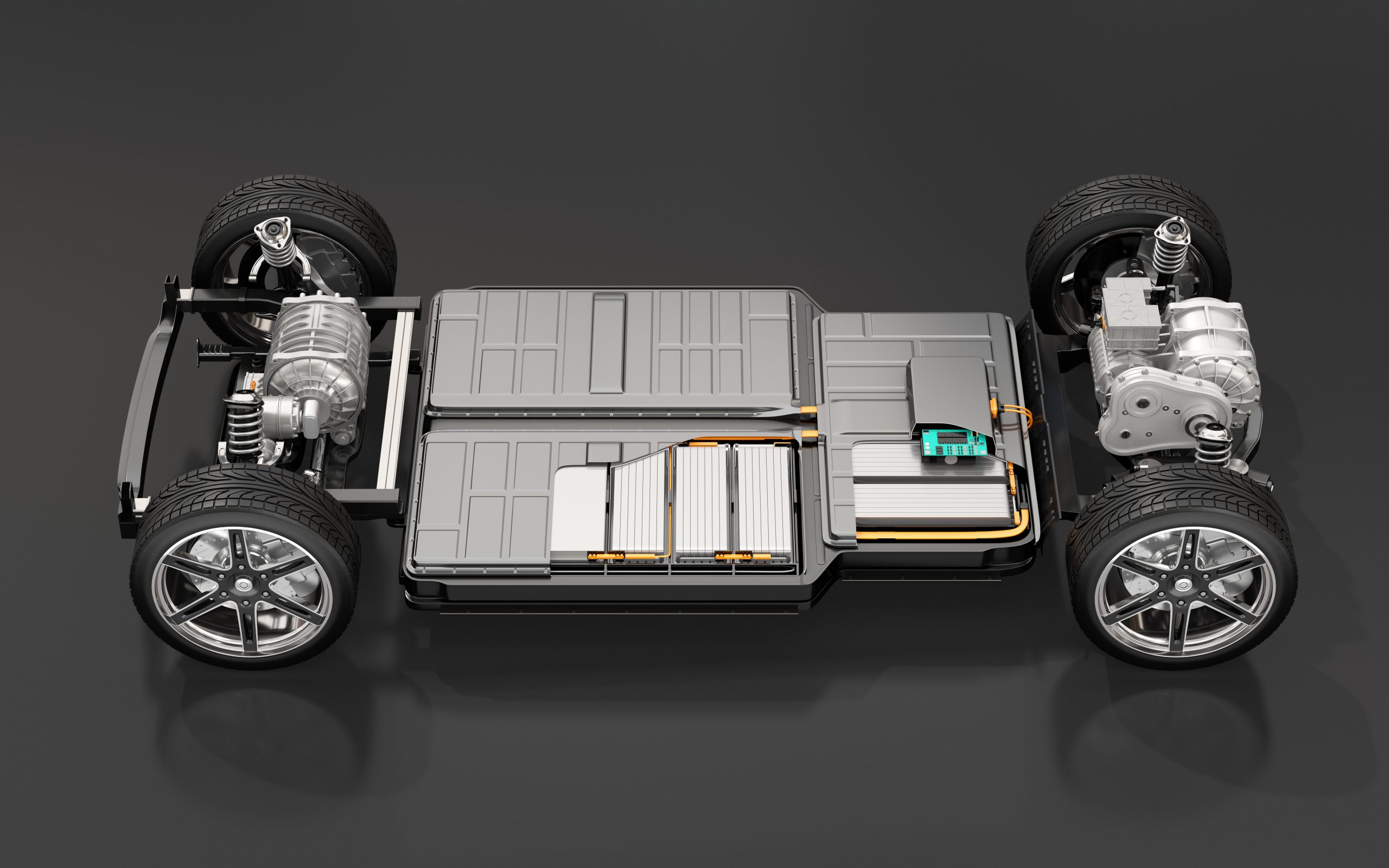
With the window problem solved for many common applications, the team now turned its focus to applications testing for different industries. Laser in vacuum has seen some high-quality academic research focusing on its applicability to specific industries, and academic institutes, end users, and manufacturers across the globe have conducted their own testing. All that said, LiV welding currently has low market penetration, though ever more organisations are beginning to see its benefits over their current process of choice (be it EB, standard laser, or even multi-pass SAW). Due to this currently low uptake rate and the sheer number of possible uses for the technology, most have not been tested. Of these applications, especially processes where EB is the incumbent, most do not need extensive testing to produce welds matching or exceeding the required quality. This is due to the stability and robustness of the LiV process, with welds being defect-free as standard, and the similarities in weld profile between EB and LiV.

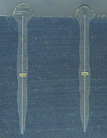
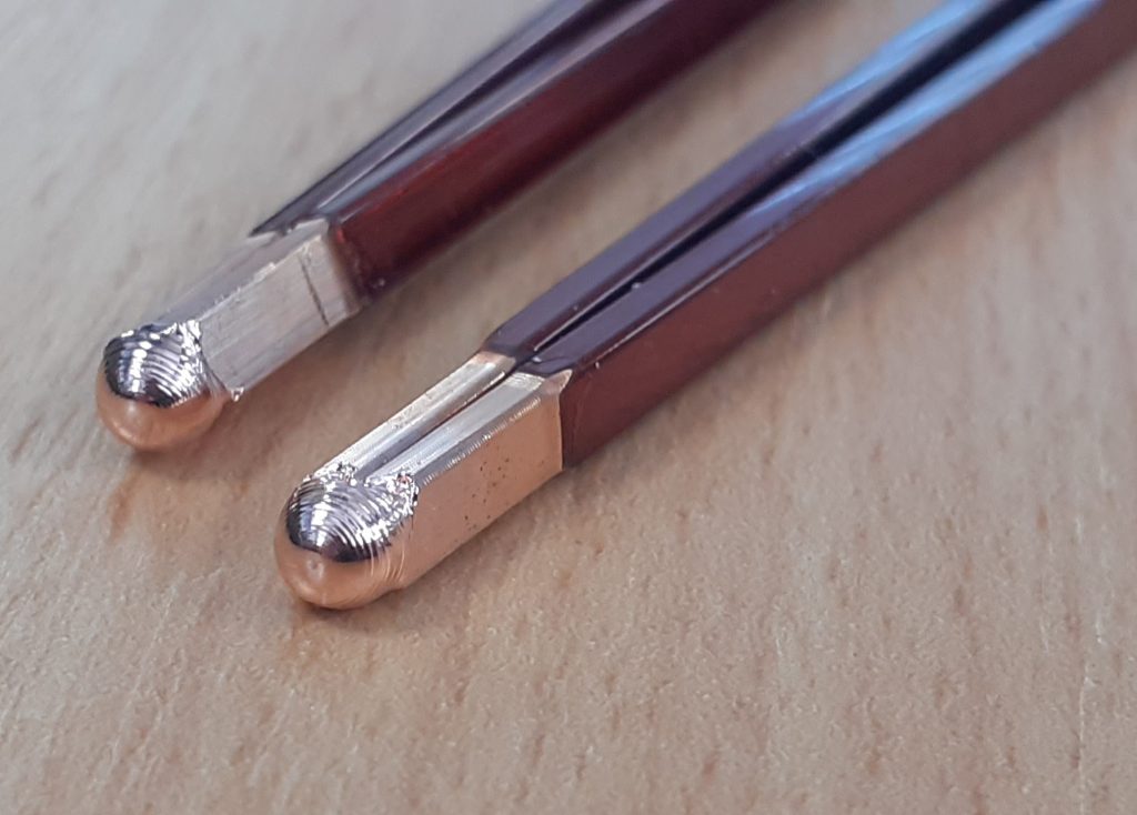
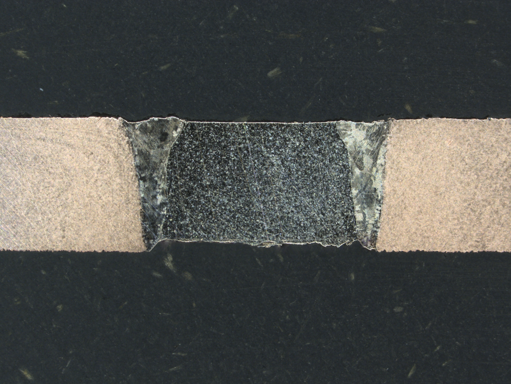
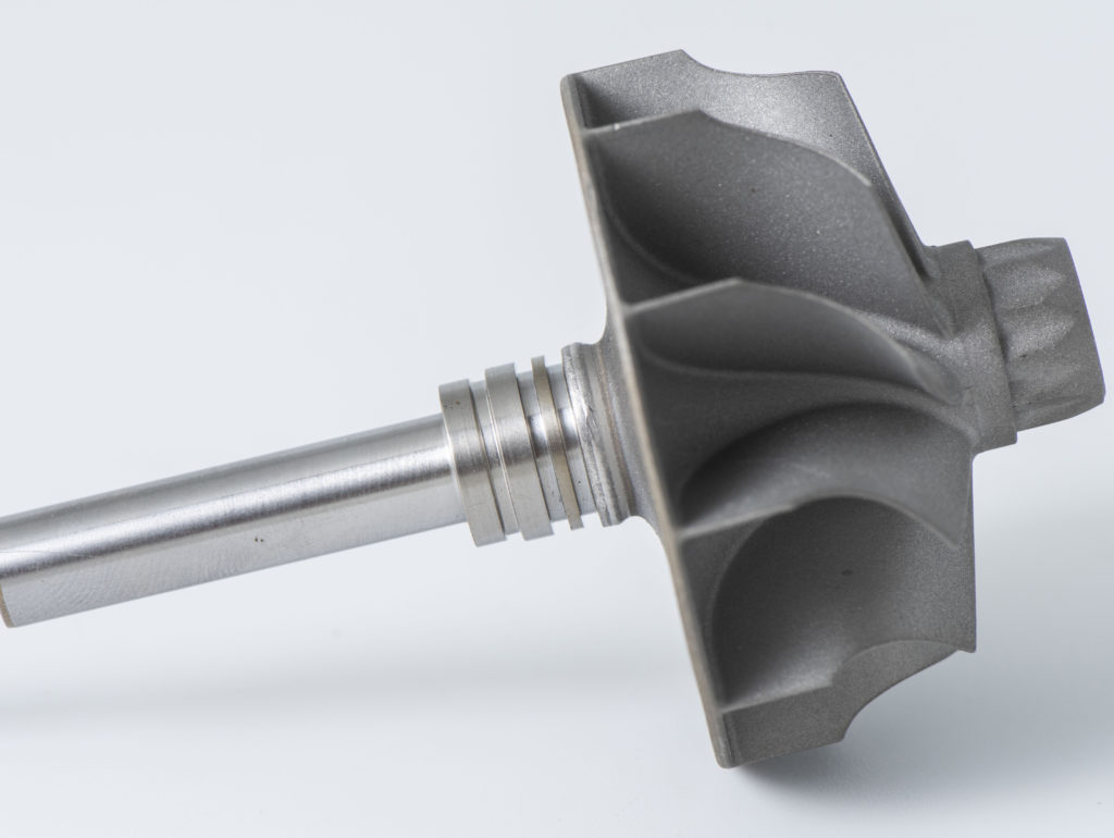
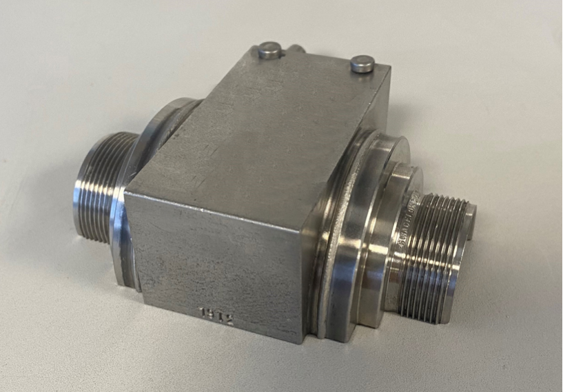
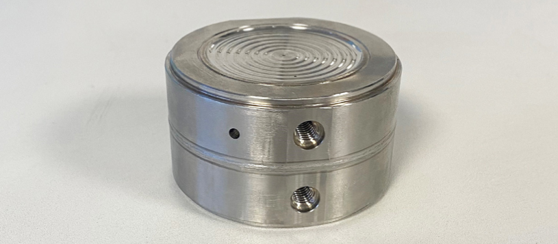
The applications testing performed has ranged from very shallow sub-mm to over 30mm penetration welds. The process of translating variable process parameters (speed, power, oscillation, spot size etc.) into weld features conforming to specific requirements (minimum/maximum weld height/underfill, half-depth width, penetration depth, root radius etc.) is not always a simple one and can require significant process understanding. Fortunately, this understanding is built upon by each application tested and the partnership has now built a strong base of knowledge about the optimal ways to achieve desired results in a diverse range of applications.

Throughout the project, the team has been using every new development or piece of knowledge to benefit running client contracts and to provide new options for interested clients. With a strong base of technical process knowledge and proven solutions to previously critical challenges, the partnership is now working to realise the potential of this powerful new tool in the joiner’s arsenal.

Highlights

The project has had many great moments worth celebrating. The successful test of the soot-free window protection system was a great milestone, providing a solution to one of the thorniest two-pronged challenges facing vacuum laser welding.

Another great pleasure was the conference and workshop presentations over the past year, at the IIW 2022 Annual Assembly in Tokyo and at the High Power Laser Welding workshop organised by the Association of Industrial Laser Users at the Manufacturing Technology Centre. These meetings were much-valued opportunities to share our progress with the wider welding community, and we are very grateful to the host organisations.

A further highlight was the nomination for the KTP Future Leader award, a great honour and privilege to see some of the other ground-breaking KTP projects currently running.

Figure 5. IIW Conference.

Looking Ahead

The future for laser in vacuum welding is bright, many industries could benefit from the quality-level and flexibility provided by laser in vacuum.

The energy and time savings the technology represents for thicker sections are very significant and could prove crucial to lowering the carbon footprint of manufacturing sustainable energy infrastructure.

The full potential of LiV is yet to be realised, but many of the barriers present just a few years ago have now been removed by the hard work of multiple research and commercial organisations.

The number of papers published on the topic per year has risen dramatically over the last 5 years, and the readiness of the technology is beginning to be noticed in industry.

As with most new technologies, progress is incremental and contributions are made by a host of different people and organisations from across the world, until the technology is finally ready for true implementation and its usage sees sudden and rapid growth.

Laser in vacuum welding has reached this ready point, and we look forward to realising the benefits it will bring to our customers.

The KTP is funded by Innovate UK and in collaboration with Cranfield University.


Italian Leaders in Electron Beam Welding

Introduction

Celsia is based near Lake Maggiore, in the Verbania area of northern Italy, situated between Milan and the Swiss border (specifically in Anzola d’Ossola).

Established in 1963 by Silvio Tedeschi and Antonio Bionda, the production plant started out as a manufacturer of low-voltage electrical contacts, aided by the know-how and the technology of its associated company, FILMS.

Towards the end of the 1960s, Celsia began producing composite materials made through infiltration (silver/tungsten and copper/tungsten), both for the electrical and electro-mechanic sectors.

Production Plant

Today, the ISO 9001 and ISO 14001 certified production plant has a range of tungsten-based sinters, brazing alloys and electrical contacts for medium and high voltage applications; the plant supplies some very high-profile clients, including ABB, Schneider, Siemens, Luxottica, Gerdau and Toshiba, amongst others.

In terms of sintered parts, the plant manufactures electrodes for the production of electro-welded wire mesh, electrodes for diamond tools sharpening, and electrodes for EDM die-sinking machines.

With regard to electrical contacts, the Celsia range includes electrical contacts for medium and high voltage switches and electrical contacts for medium and high voltage disconnecting devices.

Finally, for brazing alloys, the products on offer supply the goldsmith, glasses-making, clock-making and precision mechanics industries.

Electron Beam Welding

In its production, Celsia employs, as well as silvering and copper plating (a process through which items or components are coated with a thin metallic layer), electron beam welding (EBW), a fusion welding technology in which an electron beam hits at high speed the surface of the welding pieces and penetrates into their material.

The kinetic energy of electrons is transformed into thermal energy, which can be used for materials processing. The electrons are emitted by a heated gun. A vacuum must be produced and maintained in the entire beam generator area and in the working chamber in order to avoid too strong a divergence of the electron beam caused by the collision of the electrons with the air molecules.

The high energy concentration in the focal point of the electron beam results in a very high power density (the power density is 100 to 1000 times higher than in arc welding methods) and means it is possible to weld different materials with each other. Furthermore, the electron beam is, by means of the electromagnetic fields, deflected almost without inertia, which leads to the generation of extremely high-frequency oscillation movements entailing different welding advantages.

Through the high power density of the electron beam the energy input into the part is relatively low, which leads to almost distortion-free joining of finished products.

Cambridge Vacuum Engineering

The CVE Model CW60.15 recently purchased by Celsia has some outstanding features, including a 60 kV electron gun with a turbo-molecular pumping system, a filament alignment jig for accurate and repeatable filament change, a 15 kW switch mode power supply and beam deflection. Furthermore, it also boasts a focus and function generator, a 450 mm cube chamber and an enhanced fully automatic pumping system for operating in the 10-4 mbar range.

The machine has two separate pumping systems for the work chamber and the electron gun. The chamber can operate in either high vacuum (10-4 mbar range) or low vacuum (10-2 mbar range). Another feature is that an isolating valve is incorporated in the gun column so that the gun is maintained at high vacuum when the chamber is vented. This model enables the welding of materials with a thickness of up to 40 mm. Moreover, the distance between the welding gun and the work-piece (the stand-off distance) can reach 70 cm.

Figure 1. CVE model CW 60.15

Article courtesy of OMCD Group. Published 23 February 2017. https://www.omcd.it/italian-leaders-in-electron-beam-welding/.

Innovative Laser in Vacuum Window Protection Solution

Innovative Laser in Vacuum Window Protection Solution

Laser welding in a vacuum is an excellent process that delivers deep and high-quality welds.

But laser coupling-in window contamination by welding vapour is a significant challenge facing the implementation of vacuum laser welding on a large scale.

Through cutting-edge research in collaboration with Cranfield University, CVE has produced a window protection solution capable of operating effectively with very low levels of particulate generation.

Current Challenges

Many operators currently manage the window contamination problem by using a gas protection system. Operating at a low vacuum, this system uses a flow of gas to divert vapour away from the window.

However, low vacuum negates some of the advantages of vacuum. It causes the process emissions from welding to turn into a fine particulate that coats the chamber and workpiece.

This particulate is known as ‘soot’ and consists of a partially oxidised metal powder. A similar particulate also arises in atmospheric laser welding and is countered with a fume extraction system. In electron beam welding, the higher vacuum means the metal vapour can be deposited into an inert, solid, layer on the walls of the chamber.

In vacuum, proper soot extraction is a challenge due to the lack of atmosphere. The deposited powder is harmless in small quantities but begins to present a more significant risk when it builds into a thick layer. This can happen quickly when the machine is in heavy use. Airborne metal oxide powders can be toxic and present an explosion and fire risk. These risks are mitigated, but not avoided entirely, with regular cleaning. This conflict with health and safety requirements, as well as cleanliness standards, is unacceptable for many industries.

Figure 1. The soot deposited after 5 minutes of welding Ti64 using a low vacuum gas protection system.

Figure 2. The inert metal plating deposited after 3 hours of welding Ti64 using CVE’s innovative window protection solution.

A Ground-Breaking Solution

CVE’s work with Cranfield University has produced a window protection solution capable of operating effectively with very low levels of particulate generation.

This ensures cleanliness levels comparable with electron beam welding, while guaranteeing a long laser coupling-in window life. The low-cost consumable windows last for up to 3 hours of welding at low powers (3kW) with no appreciable weld degradation.

The rapid exchange system, also developed by CVE, allows window changes to be performed in seconds, keeping machine downtime to an absolute minimum.

These developments elevate the laser in vacuum process to the same level of reliability as the electron beam process and effectively eliminate the concern of optical contamination at low powers.

Figure 3. A comparison of a weld with a fresh window (left) and a window after 3 hours of welding using CVE’s window protection system. Protection is so effective that the window suffers virtually no degradation in this time.

Unleashing Potential

With this barrier removed, the potential of laser in vacuum can be fully realised as an alternative to electron beam, equal in quality, similar in cost and with key advantages depending on application.

Likewise, the quality superiority of vacuum laser over standard atmospheric laser can make an upgrade to a vacuum system very worthwhile.

An Introduction to Surfi-Sculpt and Its Applications

Overview

Surfi-Sculpt TM is a materials processing technology that manipulates an electron beam to modify surface textures so that they are more useful and efficient in industrial applications, such as for enhanced bonding of composites to metal.

With the ability to create a variety of hole and slot patterns, Surfi-Sculpt is applicable to a wide range of projects and materials.

Figure 1. Surfi-Sculpt surface.

Figure 2. Ultra-coarse surface.

Figure 3. Ultra-light surface.

Figure 4. Ultra-coarse surface.

What Are the Benefits of Surfi-Sculpt?

Computer software controls the location of the beam precisely and repeatably, making it a suitable process for manufacturing high-volume and value components, with the capacity to form several hundred features in less than ten seconds.

The process is highly flexible, offering the opportunity to design customised features in most industries, including medical, adhesive, and hydrodynamic applications.

It also works on nearly every material, including very hard materials, whilst leaving very little heat damage.

How Does Surfi-Sculpt Work?

Surfi-Sculpt works by melting substrate material using the heating action of the beam and then displacing material using the combined effects of temperature-variant surface tension and vapour pressure at the point of action of the beam.

This process is repeated or overlapped to give the desired features.

It can create a wide range of textures on the material’s surface, including cross-hatch or dimples.

Please see a range of applications below.

Shipbuilding: Marine Engine Driveshafts

A recent study into surface texturing of driveshafts for large marine engines qualified the use of surface texturing as a standard manufacturing process for high-friction rings for one manufacturer. The project created surfaces with a high-friction coefficient with a narrow range, achieved by creating hexagonal patterns and craters. The authors also concluded that the process offered improved uniformity, reproducibility, and functionality over the previous process (Gora et al., 2022).

Surface texturing has also seen successful applications in other shipbuilding applications, such as friction discs. Friction discs transfer power in engines and act as a safety device. They need to sustain a precise amount of friction: too much and the gear can be overloaded, too little and there could be premature slippage. Using surface modification, a higher and more reproducible friction coefficient can be achieved, whilst providing significant cost-savings. (Heriot Watt University, 2022).

Biomedical Industry: Orthopaedic Implants

Surfi-Sculpt can increase bio-functionality for implants and devices – such as orthopaedic bone implants – by direct processing or by treatment of moulds.

This allows for design improvements, including implant fixation, product consistency, and successful integration.


Figure 5. Orthopaedic implant.

Manufacturing: Rotational Symmetry

Many parts of common products, such as handles or axles, have rotational symmetry. Internal or external screw threads can be added using Surfi-Sculpt, as well as a criss-cross pattern for enhanced grip.


Figure 6. Rotational symmetry.

Materials Science: Surface Coatings

Surfi-Sculpt can manipulate surfaces to promote adhesion between a substrate and a coating. This could be taken advantage of in several industries including aerospace, medical, and automotive.


Figure 7. Surface coatings.

Acknowledgements

Surfi-Sculpt is a trademark of TWI Ltd.

Gora, W., Carstensen, J., Wlodarczyk, K., Laursen, M., Hansen, E. and Hand, D., 2022. A Novel Process for Manufacturing High-Friction Rings with a Closely Defined Coefficient of Static Friction (Relative Standard Deviation 3.5%) for Application in Ship Engine Components. Materials, 15(2), p.448.

Heriot Watt University. 2022. Laser textured discs improve marine engine performance. [online] Available at: https://www.hw.ac.uk/news/articles/2022/laser-textured-discs-improve-marine-engine.htm.

Welding Electrical Conductors for Electric Vehicles

Removing the Bottleneck in Welding of Electrical Conductors for Electric Vehicles

The need to increase the rate of joining electrically conducting components within the electric vehicle sector has become of critical importance as it is emerging to be the bottleneck of manufacturing.

The components of significance are electrical connectors and wires which can be sub millimetre thick foils or several millimetre thick rectangular section wires.

The material most used for these components is copper due to its low cost, high electrical conductivity, and plentiful availability. The high thermal conductivity of copper and low thermal input required for the components in proximity of the joining processes leads most manufacturers to choose laser welding for their high throughput manufacturing.

Laser Welding of Copper

Laser welding of copper is challenging primarily due to the wavelengths of commercially available lasers typically being red and infrared, these do not easily couple into copper due to the high reflectivity.

The reflectivity also contributes to limit the beam angle of incidence, meaning the process must integrate mechanical repositioning of the welding head.

The short focal depth of field of a welding laser also creates a high failure rate in the manufacturing, it requires high precision of machines in the manufacturing line to ensure the parts are prepared and held accurately at the correct working distance so that the weld executes correctly, repeatably.

These drawbacks experienced when laser welding copper are issues that are not relevant to electron beam welding.

Figure 1. Motor stator with 192 welds.

Figure 2. Copper hairpins.

Electron Beam Welding

Electron beam welding suffers no reflectivity issues to prevent it coupling into materials, the focal depth is multiple times longer and is rapidly adjustable during the process as the focusing is performed by electromagnetic coils.

The rapid speed of beam positioning by electromagnetic coils and commercial availability of significantly higher beam power supplies are the most important advantages in allowing electron beam to process hundreds of copper welds per minute.

The rapid rate of processing means the seconds taken for the vacuum chamber to evacuate ready for welding become negligible, furthermore, the fact that the welds are performed in a vacuum chamber mean the resulting weld has no porosity and impurities in the connection, giving the best electrical performance and vehicle efficiency.

Further Information

We build electron beam welding machines to order, and options include custom and precision work handling, vacuum systems tailored to specific process needs and productivity, wire-feed, automatic joint finding, backscattered electron imaging, automatic focus, alignment and stigmator adjustment, high-speed data capture, beam probes and QA reporting.


This paper was presented at the 75th International Institute of Welding (IIW) Annual Assembly and Conference in Tokyo, Japan. Doc.IV-1506-2022 Removing The Bottleneck In Welding Of Electrical Conductors for Electric Vehicles, Alex O’Farrell, UK.

Strip Welding Machine for Shunt Resistors

Overview

Cambridge Vacuum Engineering (CVE) offer a variety of electron beam welding systems for the manufacture of shunt resistors used in the battery management systems of standard fuel, hybrid, and electric vehicles.

Background

A shunt resistor measures electrical current by calculating the voltage drop over the resistor. In high power applications, or where high mechanical strength is required, the shunt resistors are typically comprised of a tri-metallic strip that has been electron beam welded together. The outer strips are made from Copper with the central resistive strip typically being of a Copper-Manganese (Manganin) alloy and the thickness of the strips can vary from 1 to 5mm (other resistive alloys or material thicknesses can be used).

The main application for shunts is within the battery management systems of most type of automobiles: including standard fuel, hybrid, and electric vehicles. Shunt resistors ensure the batteries are performing optimally and prolong battery life.

With the global trend in the automotive market towards electrification, the demand for battery and related products has never been greater.

Typically, shunts are manufactured in large volumes using lengths of coiled metallic strips welded together using a continuous electron beam welding system, often with two electron beam guns working in combination.

This system requires coil management and processing systems, both upstream and downstream of the welding line. CVE can offer such continuous strip welding systems.

Project

A large multinational company, headquartered in Asia, were looking for a batch welding system to enable them to manufacture shunt resistors in smaller volumes and therefore could not justify the initial investment in a traditional continuous trimetallic strip electron beam welding system.

It was important that they had a flexible system so that they could swap between part types/sizes easily, maintain high throughput rates, whilst at the same time keep high levels of accuracy and weld quality essential for the client’s potential battery and automotive customers.

Following initial weld studies with various electron beam manufacturers around the world, and having proven our welding experience and capabilities, CVE were chosen to design and build the world’s first dedicated batch strip welding machine.

Solution

As electron beam technology experts, CVE were able to design a unique machine that met the customers’ requirements by drawing on our experience of welding bimetallic and tri-metallic strip and extensive knowledge of building robust high-volume electron beam welding machines capable of working efficiently and effectively within the rigours of a heavy duty cycle environment, whilst maintaining highly repeatable weld results.

CVE delivered a 60kV, 10kW machine capable of producing up to 167mA of beam current. Welding was carried out via a fully automatic X-table, capable of moving at 50 mm/s where the parts were loaded and unloaded via a quick-release jig to hold the component strips together.

Mechanical alignment systems were in place to ensure repeatable positioning under the electron gun.

To compensate for potential issues with the part dimensions not being repeatable, CVE provided a unique dual backscattered electron joint finding system.

This system can simultaneously scan and record the joint position of both joints at full speed, ensuring that on the following tack and welding processes the beam was accurately placed on the joint via the high-speed deflection coils in the electron gun column.

It also provided linkage to internal MES part traceability systems, along with remote diagnostic support functionality as part of the customer’s quality management and maintenance system requirements.

The entire system was installed with extensive training provided, in conjunction with our local engineering team in the region as part of CVE’s commitment to global customer support.

Figure 1. Batch electron beam welding system.

Batch model of electron beam welding machine weld cross-section

Figure 2. Repeatable weld profile with no weld defects or surface imperfections.

Conclusion

CVE can adapt and provide technological engineering solutions that most other companies are either unable or unwilling to provide, ensuring customers have a bespoke electron beam welding system that they can rely on. Along with confidence that they have continuing fast, local support for the life of their machine.

The machine enabled the customer to quickly win new business in this fast-growing market. Having seen the initial batch system in action, they have decided to invest in additional batch production welding lines for their other global facilities.

Applications of 60kV Systems

Introduction

CVE’s 60kV electron beam welding machine range is ideal for welding small-to-medium-sized components at high efficiency.


60kV machines are suitable for all metals including those with high thermal conductivity, such as:

  • Steel and stainless steel
  • Aluminium and its alloys
  • Nickel alloys and refractory metals
  • Titanium and its alloys
  • Zr, Mo, Ta, Hf, W, Nb, etc.


The low heat input means that sensitive internal electronics packages may be sealed in the device without harm.


Please find a detailed list of industries and components below.


Aerospace
  • Jet engine components (figure 1)
  • Sensors and structures
  • Transmission parts


Automotive
  • Gears
  • Transmission parts
  • Turbocharger parts (figure 2)

Figure 1. Nickel-based alloy fuel spray nozzle for an aero-engine.


Electronics
  • Encapsulated electronics
  • Heatsinks
  • Parts in copper material


Medical
  • Instruments
  • Implants
  • Surgical tools


Nuclear
  • Fuel housing
  • Instrumentations
  • Valves (figure 3)

Automotive turbocharger component shaft and wheel collet

Figure 2. Inconel, MAR and carbon-steel turbocharger shaft wheel assembly.


Power Generation
  • Combustion chambers
  • Sensors
  • Vanes


Oil and Gas
  • Mining tools
  • Exploration sensors
  • Valves


Semiconductor
  • Heaters and plates
  • Showerheads
  • Surface modifications


Figure 3. Stainless steel valve body.


Space
  • Sensors (figure 4)
  • Titanium tanks


Vacuum Systems
  • Chambers for drying or coating
  • Thermal vacuum chambers


Welding of metals with dissimilar melting points
  • Copper to steel
  • Copper/steel to nickel alloys
  • Steel to Inconel
  • Tantalum to tungsten

Figure 4. Pressure sensor.


Machine Types

CVE have two 60kV machine types, ECO and CW.

The ECO model has a modular, flexible design to enhance production capabilities. The ECO is ideal for welding small-to-medium-sized components, with a small footprint and high-efficiency.

The CW model has a modular, flexible design to enhance production capabilities. The CW is ideal for the welding of medium-sized components and is suitable for thermally conductive materials.

Electron Beam Welding of Busbars for Electric Vehicles

Introduction

Busbars are an essential component of an electric vehicle.

Typically made of conductive alloys such as aluminium, bronze, or copper, they distribute power between individual cells, as well as the battery packs to the motors.

CVE, designers and manufacturers of electron beam and laser welding process solution systems, have collaborated with TWI, membership-based research and technology organisation, to explore the feasibility of using the electron beam welding process for interconnection of cells and for joining busbars to the powertrain.

Background

The structure of a typical electric vehicle battery pack starts as a cell. Designs vary across manufacturers, but the industry has settled on 21700 cells as standard.

Battery packs welded together with busbars, typically 60-100 cells, create a module, and multiple modules (6-40) make a pack.

The welded busbars are typically produced from copper with nickel plating.

This new design represents a challenge for OEMs. The components are rapidly developing and replacing traditional components that have been manufactured for hundreds of years.

The International Energy Agency predicts that there will be 230m electric vehicles worldwide by 2030, signalling an industry requirement for a high-quality, reliable, and quick welding process for battery pack production.

Wide Angle Deflection Electron Beam Welding

CVE and TWI ran a series of test welds using a method of wide-angle deflection electron beam welding.

Electron beam spot melting trials on a 450-micron steel sheet (bus bar battery tab) showed that the test welds achieved a consistent depth of up to 200 microns.


Figure 1. 60kV, 2mA, 2msec spots.

Solution

CVE and TWI successfully developed high-quality welds joining bus bars to battery cell samples.

The investigation also found electron beam welding to be a much quicker process in comparison to resistance and laser welding.

The typical time to manufacture one battery pack using resistance welding is 12,000 seconds and 1,260 seconds using laser welding. In comparison, electron beam welding has demonstrated a speed of just 189 seconds per battery pack, with anticipated developments expected to take this number closer to just 75 seconds per pack, representing a 99.38% time saving.

The weld time comparison across resistance, laser, and electron beam welding results are shown in the table below.


Time to weld one cell (4 welds) Time to manufacture one battery pack
Typical for resistance welding 4 seconds 12,000 seconds
Typical for laser welding 0.42 seconds 1,260 seconds
Demonstrated speed for electron beam 0.063 seconds 189 seconds
Anticipated electron beam development 0.025 seconds 75 seconds


Applications and Further Developments

There are many other advantages of electron beam welding for this application, including:

  • The weld quality is highly consistent
  • Electron beam welding is at least 10x faster than laser
  • There is no requirement for gas
  • Potential to implement vacuum load-lock systems
  • The vacuum chamber contains the welding process. This results in less spatter, so the welds are greatly more consistent than when using laser welding
  • An electron beam is less sensitive to reflectivity, the beam being a finely focused stream of electrons, rather than monochromatic coherent light (photons) like a laser
  • The vacuum environment closes micro-gaps, resulting in a stronger weld


Electron beam welding is already a well-established process for high-volume automotive components, such as turbochargers.

Production possibilities include implementing a vacuum load lock system, which would allow for high-speed cycles between assemblies, therefore resulting in very fast cycle times being readily achievable.

Contact Us Now

If you would like to know more about our products or speak to a member of our team, please do not hesitate to contact us. We will be happy to assist you.