Electron Beam Welding of Stainless Steels
Introduction
This case study explores electron beam (EB) welding of stainless steels, including weld characteristics, joint design considerations, and examples of welded stainless steel components.
Contents:
1. Conventional Electron Beam Welding
2. Characteristics of an Electron Beam Weld
3. Joint Design Considerations
7. Conclusion
1. Conventional Electron Beam Welding
Electron beam welding uses a stream of finely focussed electrons to melt and fuse joint surfaces. It is a contactless and reactionless process, as there are no forces engendered in the workpiece by the impinging electron beam, even though the concentrated energy density is very high. Electron beam welding principles and some aspects of the technology, which permits intricate and complex fabrications in various materials and material combinations, are discussed below.
A conventional electron beam welding machine, as shown in Figure 1, consists essentially of a device for producing a focussed beam of electrons (an electron beam column) mounted on, or in, an evacuated chamber that contains devices for holding and moving a workpiece.
Electrons are generated and accelerated in the electron beam column to form a long, fine beam moving at a very high velocity. The magnetic lens then focuses the beam to produce an intense concentration of energy that can penetrate deeply into the metal. The deflection coils, situated below the focus coil, move the electron beam in circles or more complex patterns for fusion zone improvement when supplied by appropriate voltages and waveforms. The electron beam travels through the abutting surfaces, and the joint surfaces are then progressively fused – creating a weld.
The specification and combination of weld parameters determine the maximum material thickness. The weld parameters, all of which are readily adjustable, are accelerating voltage, beam current, beam focus, and transverse speed.
The high heat intensity of electron beam welding results in a very narrow fusion zone with minimal distortion (Figure 2), so it is possible to weld machined components in the finished condition.
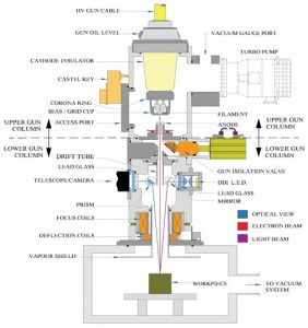
Figure 1. Schematic diagram of an electron beam welding machine.
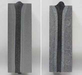
Figure 2. Cross section of 75mm thick stainless steel alloys electron beam welded in a single pass wrought (L) and cast (R).
2. Characteristics of an Electron Beam Weld
The process results in high-quality welds associated with electronic control. This precise control of the beam allied to accurate manipulation of the workpiece provides a welding process that is readily capable of being fully automated.
CVE design systems to meet requirements with work chamber and work handling systems to suit product size and throughput. Selection of high vacuum (10-4 mbar) or partial vacuum systems (10-2 mbar) depends upon weld requirements.
The control system is also dependent upon production requirements and is fully computer-controlled. Figure 3 shows a typical medium-size chamber on a CVE electron beam welding machine.
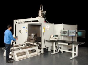
Figure 3. CVE electron beam welding machine with a medium-sized chamber.
3. Joint Design Considerations
There are several aspects to consider when designing joints for the electron beam welding process. The joint must be satisfactorily strong in service and capable of being consistently produced in the quantities and the requisite quality desired. A reliable and simple inspection method is also desirable.
A designer will be disposed towards the electron beam process when there is a requirement for EB’s unique characteristics of a deep penetration weld and low total heat input. However, it is important to note the metallurgical factors to attain satisfactory quality. For instance, you should avoid welds that only partially penetrate, as these are prone to root porosity even when using beam deflection. A weld is usually stipulated to be of full penetration with a good sized under bead (in the context of the piece part dimensions), and as such, it has the merit of being easy to inspect.
There are advantages to be gained from specifying the simplest weld shapes since remote handling is an unavoidable feature of the electron beam welding process. The component must be fixtured and moved under the electron beam, as even though you can build in an extremely complex series of motions, simple tooling motions contribute to consistent and accurate alignment in the long term.
4. Welding Stainless Steel
So far as electron beam welding is concerned, high chromium content stainless steels, noted for their corrosion and temperature resistance, can be briefly categorised as the below.
Austenitic Steels
The ‘300’ series of steels are all readily welded by the electron beam process, exhibiting near parent metal strength and fusion zones free from cracks and porosity. The inert atmosphere of electron beam welding ensures an excellent piece part appearance after welding.
Ferritic Steels
These magnetic grades with a chromium content of 17-20% are not ideal for the electron beam process. So, they may require nickel addition to the fusion zone and/or pre or post-weld heat treatment to achieve acceptable joints.
Martensitic Steels
You can satisfactorily weld annealed material, although a tendency to solidification voids and root defects typically requires parameter selection. Some martensitic steels have high carbon content, and this is detrimental to good welding performance. Precipitation hardening stainless steels of the martensitic type have good weldability but require ageing to develop parent metal properties in the weld zone.
Duplex and Super Duplex Stainless Steels
Combining the optimum properties of both the ferritic and austenitic steels, these types are reported to have good weldability without preheating or post-weld heat treatment. The addition of nickel shim may also be useful to achieve the desired ratio of austenite to ferrite for corrosion protection.
5. Practical Examples
The following examples illustrate the remarkable versatility of the electron beam welding process in a range of weld penetrations and material combinations.
Figure 4 illustrates a range of small components fabricated using electron beam welding.
An application that exploits the small electron beam cross-section is the joining of precision bellows of stainless steel to a tapered coupling.
The fixturing required before welding is of the lightest construction as no forces are involved in the electron beam process. Other examples include relays, transducers, aneroid capsules, and diaphragms.
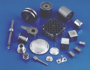
Figure 4. Stainless steel electron beam welded components.
Figure 5 shows a fuel spray nozzle for a gas turbine engine.
These nozzles are circumferentially disposed around the engine combustion chamber and spray atomised fuel at high pressure into the high-temperature burning zone.
The exit end of the nozzle is an assembly of Inconel 625 and Hastelloy, and the support stem is type 347 stainless steel.
Although Inconel may be prone to weld cracking, performing the electron beam process at a relatively slow speed ensures good mixing in the fusion zone and produces a crack-free joint.
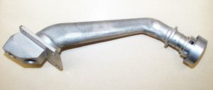
Figure 5. Fuel spray nozzle.
6. Industry Adoption
The nuclear industry was the first to adopt electron beam welding of stainless steels on a large scale to exploit the properties of a small heat-affected zone, low incidence of defects, and near parent metal strength, to fabricate fuel and coolant containers of all sizes. The tubular fabrication in austenitic stainless steel type 304L shown above contains three pieces – a hexagonal base welded to a tube with the tube itself capped by a nosepiece. The whole assembly is some 2 m in length.
The requirement is for a straight assembly without significant drooping due to contraction distortion. The solution adopted involved pre-weld tacking at low power followed by 120° of full weld depth and completed by a full-circumference weld of full-depth commenced on the opposite side to the 120° of pre-weld. The various distortions engendered by this regime cancelled each other to produce straight assemblies. The weld fusion zone was made at a sufficient level of power to over-penetrate and produce a heavy consolidated internal bead. This process was sufficiently large to be machined to parent metal diameter and give a smooth bore.
7. Conclusion
In conclusion, the electron beam welding process has the merits of:
- Deep penetration
- Narrow fusion zone of controllable shape
- Inert atmosphere (vacuum)
- Near parent metal strength
- Single-pass capability at high speed
- Autogeny, no filler metal is required
- Small heat input, low distortion
It is truly a high-quality process for joining high-quality materials.
If you are not sure which system is right for your application, please get in touch! Our machines are built and manufactured at our Cambridge Headquarters. With 60-years of process know-how in providing turn-key solutions, we can find the right solution for your application.