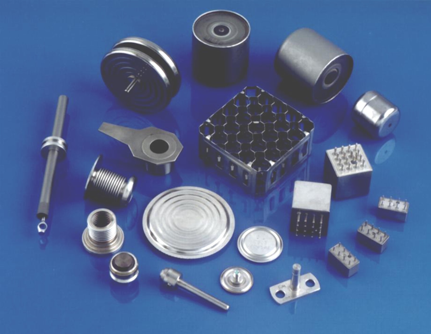
Electron Beam Welding for Defence Applications
Introduction
Electron beam welding is a well-established welding process within the defence industry due to the high-quality output that the application requires. A variety of components, ranging from small to large and simple to complex, can be welded on CVE electron beam welders.
The characteristic electron beam weld has deep penetration, a narrow fusion zone, near parent metal strength, and is made in an inert atmosphere (vacuum).
The low heat input, typically 5% of that required for other fusion welding processes, implies a small disturbance of metal near the weld zone and a correspondingly small distortion of piece parts so that you can join finished components.
Contents:
3. CVE’s Computer Control System
6. Beam Probing
Aluminium Alloys
High strength enclosures are manufactured in aluminium, utilising a combination of extrusions, CNC machining, and electron beam welding to provide a cost-effective manufacturing method.
Other examples of aluminium parts made by electron beam welding include missile cases, launchers, and armour piercing parts.
In some instances, it is possible to modify the mechanical properties within aluminium components by using a wire-feed system. An example is the local alloying of pistons around the piston ring groove.
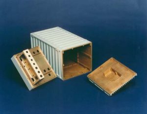
Figure 1. High integrity and dimensional stability are important requirements for this product made in 6082 TF (T6).
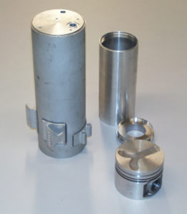
Figure 2. A selection of aluminium parts.
Waveguides and antennae are also manufactured using electron beam welding. A cost-effective method of manufacture is to weld a combination of machined parts, forgings, and extrusions. By this means, it is also possible to produce parts that cannot be fabricated viably by any other welding technique.
The impracticality of forging a one-piece structure led to the concept of fabrication using electron beam welding. Electron beam welding allows you to use simpler forgings and complete practically all machining operations before assembly.
Below is a typical system for welding aluminium parts. The system may be operated in either a high or low vacuum, and the switch mode power supply is ideally suited to the deep welding of aluminium alloys. It is a CW model with a 60kV, 15kW electron beam column and switch-mode power supply. The chamber is a 1-metre cube with CNC controlled X-Y worktable with an internal rotary tilt table and run-out platform.
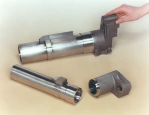
Figure 3. One-piece structures.
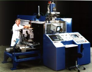
Figure 4. CVE’s CW model of electron beam welding system.
Titanium Components
Examples of titanium parts manufactured by electron beam welding include fuel propellant tanks.
Electron beam welding is used to fabricate a rigid but lightweight rotor in Titanium alloy 685.
Minimum heat input assures dimensional stability, and the close control available on weld geometry means that post-weld machining is applied only to end flanges and seal diameters.
Our XW range of electron beam welders include chamber sizes up to 5000 x 3000 x 3000mm and up to 30kW beam power at 150kV. CNC controlled work handling equipment includes an X-Y table, run-out platform, rotary tilt table, and horizontal rotary table.
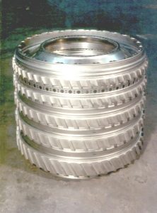
Figure 5. Lightweight rotor in Titanium alloy 685.
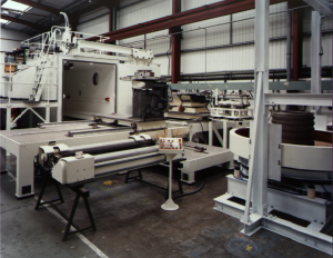
Figure 6. CVE’s XW model of electron beam welding system.
CVE's Computer Control System
The human-machine interface (HMI) includes a PC (either industrial touch-screen or keyboard & mouse) to provide a fully integrated system for controlling the beam parameters and mechanical movement. To assist the operator during set-up, CVE provides a dynamic change function.
Since the computer system monitors the key process parameters, you can use it for data logging. Software options are available for quality assurance (QA) monitoring and reporting. The QA package allows viewing of historical weld data automatically recorded. The system can display the data in a graphical form. The user may specify which parameters and timescale is displayed. You can read values from the graph and dynamically adjust the scaling.
You can save areas of particular interest a file in a format compatible with Microsoft Excel and graphically display real-time data. All beam parameters and vacuum levels are available. A record of the last weld performed can be displayed and printed. It shows the demanded values of all beam parameters and the variance from these values during the weld. You can cross-reference this information against the historical graph.
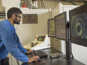
Figure 7. CVE’s HMI computer control system.
Special Systems
Special systems are normally designed for maximum production output featuring:
- Small chambers – no larger than necessary to hold one component
- Fast evacuation – very large pumps, often low vacuum
- Rapid work movement – component positioned in the chamber and manipulated very quickly
- Complete production lines – can incorporate washers, dryers, demagnetisers, presses, automatic handling, measuring and testing equipment
Joint Finding Options
Teach and Replay
This option is useful with components that have non-linear or varying weld joints and require a CNC control function.
Joint Finding
This option assists the operator by automatically finding the joint using back scattered electrons and a detector mounted in the top of the chamber. It is useful where components have multiple weld joints with minor dimensional differences between individual parts.
Seam Tracking
Seam tracking can incorporate joint finding plus a teach and replay function described above to follow the joint. It is useful for large rotary welds to compensate for run-out of the weld joint. Special software however is required to follow the joint in real time and the joint requires special preparation to be “seen” by the system. In this mode the end user must be prepared to trust the system to take over the tracking and welding of a joint automatically in real time.
Beam Probing
Electron beam welding is widely applied to high-value components and before welding, the operator must be confident that the equipment will produce the best quality weld. Reproducibility and consistency of the weld are also extremely important.
Beam probing techniques are often used as a QA method prior to welding to ensure the equipment will produce the desired quality weld. Whilst welding test pieces can confirm good beam quality the process is time-consuming and the results, if not acceptable, are difficult to interpret in terms of changes to the machine setup that may be required.
The design is based on existing proven equipment developed by TWI.
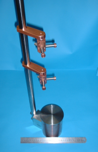
Figure 8. Beam probing system.

